ISL25700
11
FN6885.0
September 3, 2010
Device ID Register (Reg.00h)
This is a read only register. It contains device ID code 00h.
Coarse Temperature Control (Reg.01h [2:0])
These 3 bits allow one to choose one of the seven coarse
windows for the temperature set point. The default set
point is about +59癈 for the 100k R
TH
thermistor with a
temperature coefficient of -4.25%/?/SPAN>C at +25?/SPAN>C, i.e.
Reg.01h[2:0] = 011b. The temperature set point can be
changed to any other set point within an operational
range from +40癈 to +110癈, or use another type of
thermistor, including different resistance value or R/T
curve type (NTC slope), and then center the +15癈
coarse range temperature window on that new setting
based on the ratio of R
INT
/R
TH
according to Equation 1:
where:
R
INT
- is an internal 9k?resistor, forming another leg of
the Wheatstone Bridge;
K1, K2 and K3 - are coefficients representing the ratio of
the current flowing through the legs of the Wheatstone
Bridge;
Code - is the decimal code in the Fine Temperature
Control register 02h.
The value of internal resistor R
INT
can vary from part to
part and depends on the package temperature. The
actual R
INT
at temperature T can be calculated using
Equation 2:
where:
R
INT
(25) = 9000 + R
INT
abs. error x 15 - is internal
resistor value at +25?/SPAN>C in Ohms;
R
INT
abs. error - is a signed integer value of absolute
error stored in Reg.07h[7:0] converted to a decimal
number; bit [7] represents a sign bit, 0 for
+
and 1 for
-
;
- 1st order temperature coefficient,
ppm/?/SPAN>C;
- 2nd order temperature coefficient,
ppm/?/SPAN>C
2
;
T - temperature in Celsius.
The K1, K2 and K3 coefficients and the thermistor value
range for each Coarse Temperature setting in
Reg.01h[2:0] should be taken according to Table 2.
Current Sense Threshold (Reg.01h [7:3])
This register sets the current limit trip point. When the
voltage applied to the I
SENSE
pin falls below the
programmed voltage threshold, V
OUT
goes high, thus
forming a negative feedback loop proportional to I
SENSE
x R
SENSE
.
The value for this register should be taken according to
Table 3.
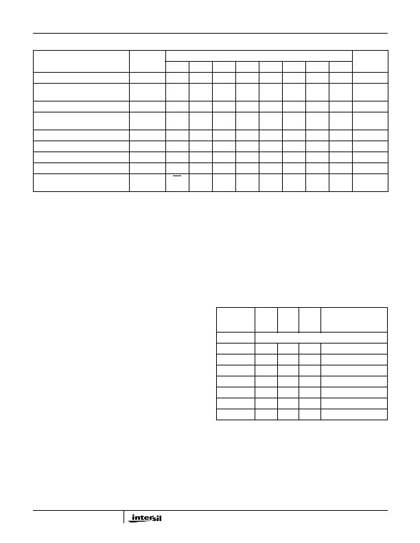
TABLE 1. ISL25700 MEMORY MAP
REGISTER NAME
REGISTER
ADDRESS
BIT MAP
DEFAULT
SETTINGS
7
6
5
4
3
2
1
0
Device ID (Read Only)
00h
ID[7] ID[6] ID[5] ID[4] ID[3] ID[2] ID[1] ID[0]
00h
Current Sense/
Coarse Temperature Control
01h
CS[4] CS[3] CS[2] CS[1] CS[0] CTC[2] CTC[1] CTC[0]
03h
Fine Temperature Control
02h
FTC[7] FTC[6] FTC[5] FTC[4] FTC[3] FTC[2] FTC[1] FTC[0]
80h
Gain Control (DAC Enable/
DAC Gain/System Loop Gain)
03h
DAC
Enable
DAC
Gain
NA
SLG[4] SLG[3] SLG[2] SLG[1] SLG[0]
90h
General Purpose DAC
04h
DAC[7] DAC[6] DAC[5] DAC[4] DAC[3] DAC[2] DAC[1] DAC[0]
80h
General Purpose Register 1
05h
GP1[7] GP1[6] GP1[5] GP1[4] GP1[3] GP1[2] GP1[1] GP1[0]
00h
General Purpose Register 2
06h
GP2[7] GP2[6] GP2[5] GP2[4] GP2[3] GP2[2] GP2[1] GP2[0]
00h
R
INT
Absolute Error (Read Only)
07h
sign bit ERR[6] ERR[5] ERR[4] ERR[3] ERR[2] ERR[1] ERR[0]
XX
Control/Status Register
(Volatile Only)
08h
NV
NA
NA
NA
NA
NA
NA
BUSY
00h
R
INT
T
( )
R
TH
setpoint
(
)
---------------------------------------- -
K2 K3
Code
255
-------------- -
?/DIV>
+
K1
------------------------------------------- -
=
(EQ. 1)
R
INT
T
( ) R
INT
25
( )x 1 ?T 25
(
) ?T 25
(
)
2
+
+
[
]
=
(EQ. 2)
TABLE 2. COARSE TEMPERATURE RANGE
Register
01h[2:0]
K1
K2
K3
THERMISTOR
RESISTANCE RANGE
AT SET POINT (k?
000
Do not use
001
3
3
2
5.4 to 9.0
010
4
3
2
7.2 to 12.0
100
5
3
2
9.0 to 15.0
011
7
3
2
12.6 to 21.0
101
8
3
2
14.4 to 24.0
110
9
3
2
16.2 to 27.0
111
12
3
2
21.6 to 36.0
?nbsp 1337
6
?0
=
?nbsp 5
6
?0
=
发布紧急采购,3分钟左右您将得到回复。
相关PDF资料
ISL6150IB
IC CTRLR HOT PLUG NEG VOLT 8SOIC
ISL6151IB-T
IC CTRLR HOT PLUG NEG VOLT 8SOIC
ISL6160CB-T
IC CTRLR BULK/AUXILIARY 14-SOIC
ISL6161CB-T
IC CTRLR PWR DISTRIB DUAL 14SOIC
ISL6173DRZA-T
IC CTRLR HOT SWAP DUAL LV 28-QFN
ISL6174IRZ
IC CIRC BREAKER DUAL LV 28-QFN
ISL61861DCBZ
IC USB PWR CTRLR 3A 8SOIC
ISL6402IR
IC REG TRPL BCK/LINEAR 28-QFN
相关代理商/技术参数
ISL26102
制造商:INTERSIL 制造商全称:Intersil Corporation 功能描述:Low-Noise 24-bit Delta Sigma ADC
ISL26102AVZ
制造商:Intersil Corporation 功能描述:LOW-NOISE 24-BIT DELTA SIGMA ADC, OPERATION TO 4KSPS, 24L TS - Bulk 制造商:Intersil Corporation 功能描述:IC ADC 24BIT SRL 2CH 24-TSSOP 制造商:Intersil 功能描述:LOW-NOISE 24Bit ADC- 4KSPS IC------------ 制造商:INTERSIL 功能描述:ISL26102 Series Dual Ch 24-bit Delta Sigma Analog to Digital Converter TSSOP-24
ISL26102AVZ-T
制造商:Intersil Corporation 功能描述:LOW-NOISE 24-BIT DELTA SIGMA ADC, OPERATION TO 4KSPS, 24L TS - Tape and Reel 制造商:Intersil Corporation 功能描述:IC ADC 24BIT SRL 2CH 24-TSSOP 制造商:Intersil 功能描述:LOW-NOISE 24Bit ADC- 4KSPS IC------------
ISL26102AVZ-T7A
功能描述:模数转换器 - ADC LOW-NOISE 24Bit ADC 4KSPS IC
RoHS:否 制造商:Texas Instruments 通道数量:2 结构:Sigma-Delta 转换速率:125 SPs to 8 KSPs 分辨率:24 bit 输入类型:Differential 信噪比:107 dB 接口类型:SPI 工作电源电压:1.7 V to 3.6 V, 2.7 V to 5.25 V 最大工作温度:+ 85 C 安装风格:SMD/SMT 封装 / 箱体:VQFN-32
ISL26104
制造商:INTERSIL 制造商全称:Intersil Corporation 功能描述:Low-Noise 24-bit Delta Sigma ADC
ISL26104AV28EV1Z
制造商:Intersil Corporation 功能描述:ISL26104 EVAL BOARD 1 - 28 LD TSSOP - ROHS COMPLIANT - Bulk 制造商:Intersil Corporation 功能描述:BOARD EVAL FOR ISL26104A 制造商:Intersil Corporation 功能描述:Data Conversion IC Development Tools ISL26104 EVAL BOARD 制造商:Intersil Corporation 功能描述:ISL26104 EVAL BOARD 1 - 28 Ld TSSOP - ROHs Compliant
ISL26104AVZ
制造商:Intersil Corporation 功能描述:ISL26104AVZ LOW-NOISE 24-BIT DELTA SIGMA ADC, OPERATION TO - Rail/Tube 制造商:Intersil Corporation 功能描述:IC ADC 24BIT SRL 4CH 28-TSSOP 制造商:INTERSIL 功能描述:ISL26104 Series Dual Ch 24-bit Delta Sigma Analog to Digital Converter TSSOP-28 制造商:Intersil 功能描述:LOW-NOISE 24Bit ADC- 4KSPS IC------------
ISL26104AVZ-T
制造商:Intersil Corporation 功能描述:LOW-NOISE 24-BIT DELTA SIGMA ADC, OPERATION TO 4KSPS, 28L TS - Tape and Reel 制造商:Intersil Corporation 功能描述:IC ADC 24BIT SRL 4CH 28-TSSOP 制造商:Intersil 功能描述:LOW-NOISE 24Bit ADC- 4KSPS IC------------